
 Deutsch
Leng Startseite / Products / Tube bar drawing dies
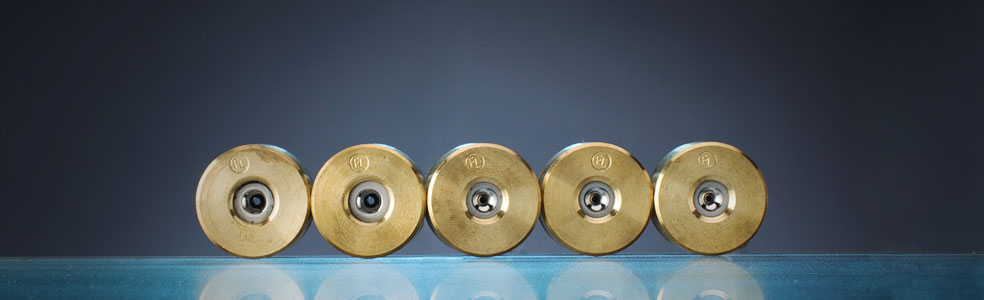
Tube bar drawing dies are used to draw strand-like drawing material.
The following factors are important for a carbide die to function trouble-free:
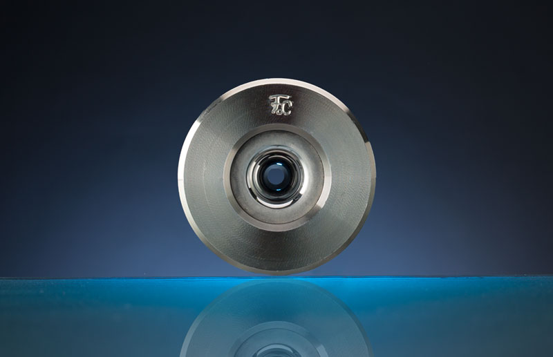
High quality carbide in the correct Grade as well as high quality steel for the case. Both have to be aligned in their composition according to the individual usage. The perfect function, as well as the lifetime of the carbide die are defined by the correct geometry of the drawing angle, the cylinder length and a high polished surface.
Calculation and CAD-software are available to determine the ideal parameters.
A variety of carbide grades, surfaces with hard coating, as well as ceramic dies are of course part of our product range
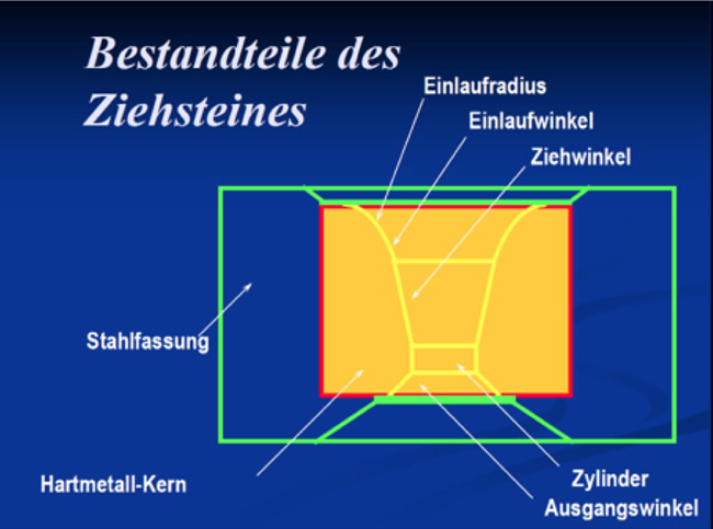
The entry radius or entry angle serves to guide the incoming wire when it enters in spirals. It guides the wire, so it enters centered into the carbide die. The Bell-angle serves the feeding of lubricants into the die. Bell radius or angle can be left unpolished.
The approach angle is the most important section of a wire drawing die. The entire reduction in area and the compacting of lubricant onto the incoming wire surface occurs here. The efficiency of any die is determined by the design and accuracy of this approach area, which must be cut to an accurate conical angle with a smooth surface finish. It must be straight sided without a distinct radius or blended contour along its entire surface.
The approach angle does all of the work in the die and must be looked at first when designing or problem solving a die. It has three major functions, which must be considered when selecting the correct angle and understanding how it works.
The approach angle’s first job is to lubricate the surface of the wire prior to reduction by producing pressure that promotes lubricant flow. Without proper lubricant pressure the die will consume the precoat and any previous lubricant film put on by other dies, which increases the risk of scratching in further drafts.
The reduction zone is where the die reduces the diameter of the incoming wire. This reduction causes the material to change its physical properties by imparting a dense structure, hard surface and improved finish. Using the wrong angle or reduction is the main cause of drawing failures and rejected wire.
Finally, the approach angle also sizes the material at the point it meets the bearing intersection. The bearing only controls the size; it does not generate the wire’s diameter. This is part of the approach angle’s job.
The guiding length purpose is to control the diameter of the drawn wire, to guarantee its roundness and straightness, as well to produce a flush and smooth surface. To produce a quality wire, the guiding length has to be round, parallel and with a minimum size tolerance. To avoid a rapid oversized fatigue of the tool the length of the bearing should be between 25 and 66% of the tool diameter. For example: A tool with a diameter of 2.54 mm and a percentage proportion of the guide length of 35%, has a guiding length of 0.889 mm. Choosing the bearing length is dependent on the hardness of the wire to be drawn and the desired lubricating film. In general, shorter bearing lengths are used for harder materials (about 25 or 35%), in order to avoid the increased risk of lubricating errors by greater heat development. To be able to use a tool as long as possible, for softer materials a guide length of 50% is used.